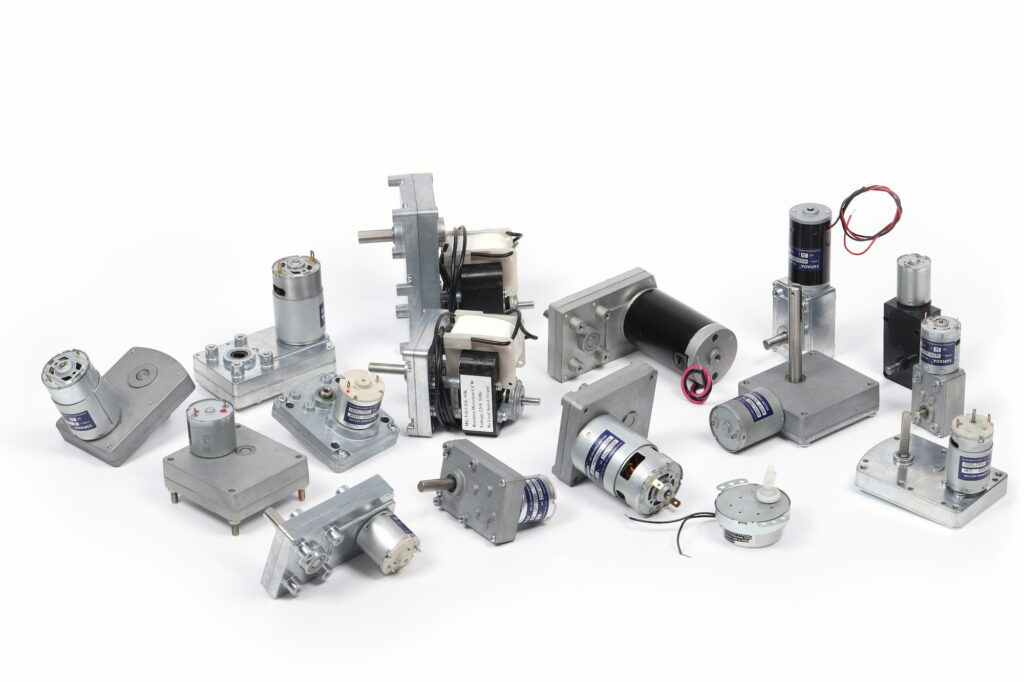
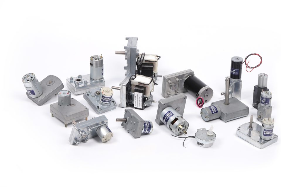
Planetary gear motor and Spur gear motor are two kinds of motor which uses a gearhead to reduce the speed of the motor and increase the torque of the motor. So that, some application needs high torque and low speed engine will consider about gear motors.
There are two main types of geared motors: planetary gear motors and spur gear motors. These two types of motors has their own advantages and disadvantages. In this article, Doncen motor will brief introduce the main defferences between planetary gear motors and dc geared motors. We hope it could help you find suitable motors.
- 1.1 What is a planetary gear motor?
- How to calculate planetart gear ratios
- 2.1 What is a spur gear motor
- How to calculate spur gear ratios
- 3.1 Differences between planetary and spur gear motors
What is a planetary gear motor?
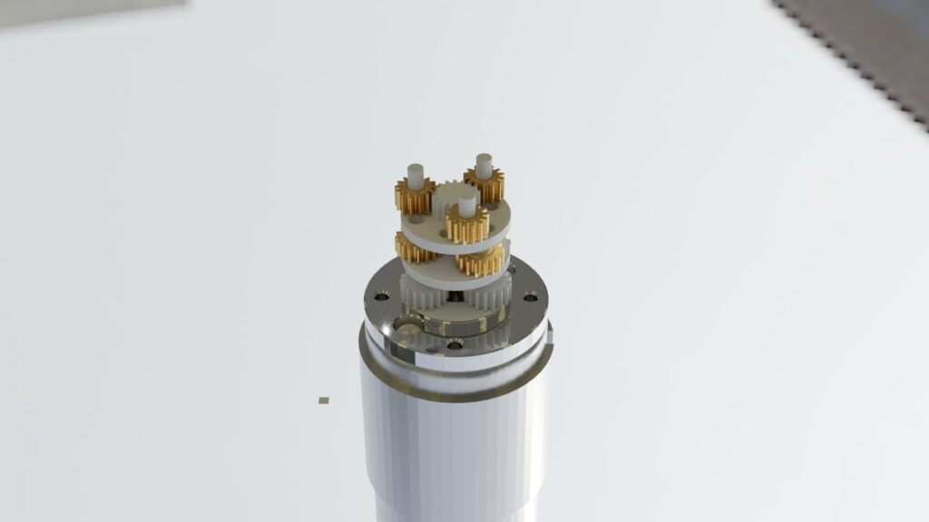
A planetary gear motor is a type of gear motor that uses planetary gears to achieve a high reduction ratio. The planetary reduction structure is mainly composed of sun gear, planetary gear, and outer ring gear. Planetary gears are mounted on a stationary carrier. Then the shaft of the motor connect with the sun gear, It will transfor the power from motor to the gearbox. The planetary gears rotate around the stationary carrier and mesh with the sun gear to achieve speed reduction. At last, the power will output from the gearboxes’s shaft.
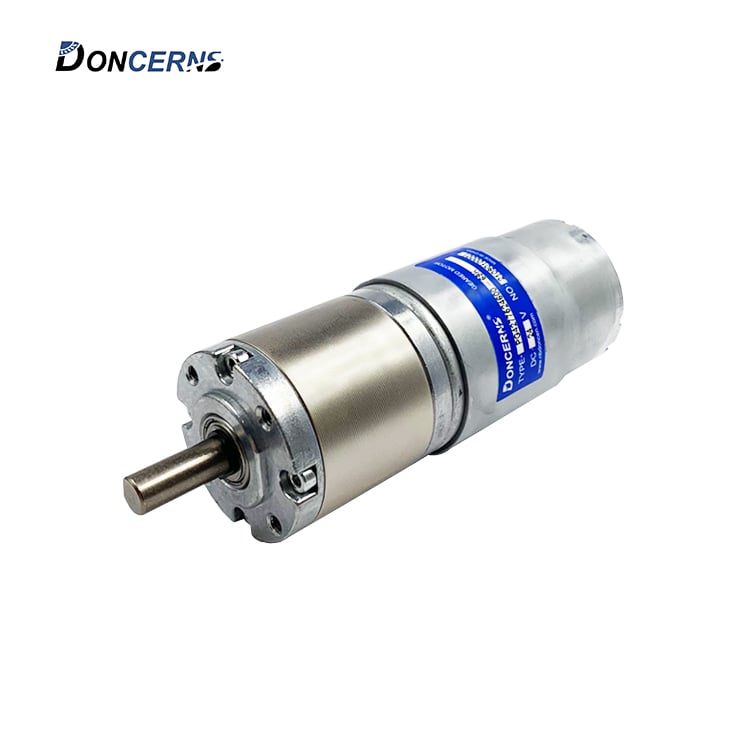
45mm Planetary Gear Motor
How to calculate the gear ratio for planetary system?
Normally, the maximum gear ratio of the first-stage planetary reduction structure cannot exceed 1:10.
Take the most basic and most commonly used 2K-H planetary gear train as an example:
Let us assume that after the gear train is running, the planet carrier rotates at a certain angular velocity W(h)
Taking the planet carrier as the stationary standard,
“angular velocity” of the sun gear: W(s)-W(h)
“angular velocity” of the Planetary gear: W(p)- W(h)
“angular velocity” of the Ring gear: W(r)- W(h)
The gear ratio could be calculated by
I=W(s)/W(h)=1+Z(s)/Z(h)
For example, taking a 2K-H planetary gear train as an example, the number of teeth of the sun gear is 15, the number of planetary gears is 18, and the number of teeth of the ring gear is 51 (15+18×2)
Gear ratio (I)= 1+51/15 =4.4
Cited from: “Planetary gear Project ” Writed by Rupesh Kumbhare 2020
What is a spur gear motor?
A spur gear is a cylindrical gear with parallel and coplanar shafts and spur teeth parallel to the output shaft. Spur gears are the simplest and most common type of gear – easy to manufacture and suitable for a wide range of applications.
The teeth of a spur gear have an involute profile and mesh one tooth at a time. The involute form means that spur gears only generate radial forces (no axial forces), while the meshing method of the teeth results in excessive stress on the teeth and high noise. Therefore, spur gears are usually only used in low-speed applications,
The profile of an involute gear tooth is the involute of a circle, and when two gears mesh, they touch at a single point where the involutes intersect. As the gear rotates, the point moves along the flank and the lines of force (called lines of action) are tangent to the two base circles. Therefore, gears obey the basic laws of gearing, which state that the ratio of the angular velocity of the gears must remain constant throughout the mesh.
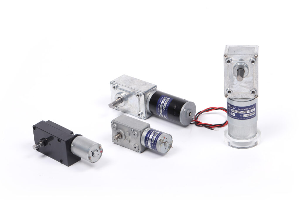
A spur gear motor is a type of gear motor that uses spur gears to achieve a high reduction ratio. Spur gears are the most common type of gear and are composed of two or more interlocking gears that rotate around a common axis. The gear ratio is determined by the number of teeth on each gear.

Spur gear motor
How to calculate the gear ratio for spur gears system?
Formula Transmission ratio = number of teeth of driven gear/number of teeth of driving gear = speed of driving wheel/speed of the driven wheel
i=z2/z1=n1/n2
Gear ratio size:
i12=N1/N2=Z2/Z1
Take the “-” represent the Steering External meshing steering.
Internal gearing is the same, take “+” sign
The transimission formula for cylindrical gear transmission, the steering relationship between the driven wheel and the driving wheel as shown:
i12=±z2/z1
Among them, the “+” sign indicates that the main driven wheel turns the same for internal meshing;
The “-” sign indicates that the main driven wheel turns in an opposite direction, which can be used for external meshing. For bevel gear transmissions and worm drives because it’s not on exactly same plane as rotational movement; so you cannot determine its speed using + or – numbers method but instead have to use drawing arrows when determining these types ofdriveways.
For rack and pinion transmission, if ω1 represents the angular velocity of gear 1, d1 represents the diameter of the index circle of gear 1, and v2 represents the moving speed of the rack, the following relationship exists: V2=d1ω1/2
Main differences of these 2 motors
Price: Planetary gear motors are higher than Spur gear motors
Noise: Planetary gear motors are silencer than Spur gear motors
Efficiency: Planetary gear motors are higher than Spur gear motors
Size:Same
Working Life: Same

