What is a Hall sensor
Hall sensor works based on the Hall effect principle and is able to detect the presence, direction and intensity of a magnetic field. The Hall sensor is an important component of the Brushless DC motor. It plays an important role in the driving of brushless motors. This article will introduce in detail the working principle and role of Hall sensors, and analyze whether brushless motors should carry Hall sensors.
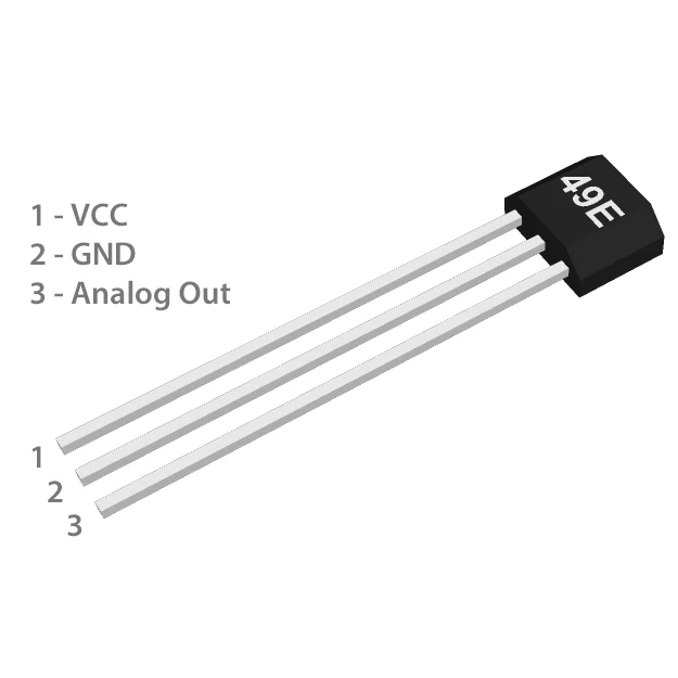
Hall Sensor Working Principle
The working principle of the Hall sensor is based on the Hall effect. When the current passing through the Hall element is affected by a magnetic field in the vertical direction, it will be affected by the Lorentz force, causing the charges to shift sideways, resulting in an imbalance in charge distribution. This imbalance creates a potential difference on both sides of the Hall, called “Hall voltage”.

Figure 1 shows the internal structure of a basic 3-pole brushless DC motor. Three-phase BLDC motors are typically equipped with three Hall sensors arranged at physical angular intervals of 120 degrees to continuously monitor the position of the rotor.
During the rotation of the motor, each Hall sensor will produce 2 high and 2 low level changes, which means that in a complete 360-degree rotation, H1 , H2 , H3 will produce six signals. The combination of these signals provides the BLDC controller with precise information about the rotor position.
Function of Hall signal
- Rotor Position: The signal generated by the Hall sensor directly indicates the position of the rotor’s magnetic poles. The controller uses these signals to determine when and how to change the direction of the current in the stator windings to push the rotor to continue rotating.
- Reversal Point: Each change in the Hall signal marks a reversal point, the moment when the direction of the current needs to be changed.
- Speed Information: By measuring the frequency of the Hall sensor signal, the speed of the motor can be derived.
Signal Output Example
Assume that the three Hall sensors are labeled H1, H2 and H3 respectively. They will output 6 different states when the motor runs 1 circle.
| State | H1 | H2 | H3 |
|---|---|---|---|
| State 1 | HIGH | LOW | LOW |
| State 2 | HIGH | HIGH | LOW |
| State 3 | LOW | HIGH | LOW |
| State 4 | LOW | HIGH | HIGH |
| State 5 | LOW | LOW | HIGH |
| State 6 | HIGH | LOW | HIGH |
These six states cycle through and provide continuous position feedback to the motor controller, allowing it to perform precise commutation operations.
Types of Hall Sensor in BLDC Motor
1. Linear Hall Sensor
Features: Linear Hall sensors output a continuous voltage signal proportional to the detected magnetic field strength.
Application: Used to accurately measure magnetic field strength, such as in position sensing, angle sensing, current measurement, etc.
2. Digital Hall Sensor
Features: The digital Hall sensor outputs a high level (or low level) when the magnetic field reaches a predetermined threshold, and outputs a low level (or high level) when the magnetic field is lower than another threshold. This type of sensor is used to detect the presence or absence of a magnetic field.
Applications: Widely used in position detection, speed detection and rotary encoders, such as electronic commutation of brushless DC motors (BLDC), crankshaft and camshaft position detection in automobiles, etc.
Advantage of Hall Sensor
Brushless DC motors (BLDC) can be classified according to whether they have integrated Hall sensors. Engineers can choose whether to use Hall sensors based on their application needs.
| Feature | With Hall Sensors | Without Hall Sensors (Sensorless) |
|---|---|---|
| Position Sensing | Accurate rotor position detection, essential for precise electronic commutation. | Relies on motor electrical signals (e.g., Back EMF) to infer position, lacking direct position feedback. |
| Startup and Low-Speed Control | Simpler and more reliable, especially at startup and low speeds due to direct position information. | More complex and potentially less reliable control strategies required for smooth startup and low-speed performance. |
| Control Simplicity | Simpler control algorithms due to direct position feedback, resulting in smoother startup and operation. | More complex control algorithms needed, especially for startup and low-speed operation without direct rotor position. |
| Cost and Complexity | Higher cost and increased manufacturing complexity | Reduced cost, weight, and size by eliminating sensors |

